Draw the Shear and Moment Diagrams for the Shaft
Draw the shear and moment diagrams for the shaft in terms of. B and c respectivelyAs indicated on the moment diagram The moment of inertia of the cross-section about the neutral axis is Here Thus Ansd 1908 in 2 in.

Statics 7 45 Draw The Shear And Moment Diagrams For The Shaft In Terms Of The Parameters Shown Youtube
The bending stress distribution for bending about z and y axes are shown in Fig.
. Draw the shear and moment diagrams for the shaft if it is subjected to the vertical loadings and determine the maximum bending moment in N-m. Draw the shear and moment diagrams for the shaft if Need more help. Draw Shear force diagram and bending moment diagram 2.
2 ft 3 kip. Draw the shear and moment diagrams for the beam. Maximum -ve Bending Moment Mmin -6000 kN-mm at x 250008 mm from the left end.
The bearings at A and B exert only vertical reactions on the. The support at A is a journal bearing and at B it is a thrust bearing. Choose suitable material for the shaft and calculate the safety factor 230 mm 280 mm 30-mm dia.
200 lb ft B x 4 ft 4 ft 150 lbft 6 ft 200 lb ft A Ans. P 9kN a 2 m L 6 m. Also express the shear and moment in the shaft as a function of x within the region 125 mm x 725 mm.
Draw the shear and moment diagrams for the shaft. 40 Building Shear and Moment Diagrams. Draw the shear and moment diagrams for the beam and determine the shear and moment in the beam as functions of x where 4 ft x 10 ft.
If aowable bending stress 30 ksi and the allowable shear stress- 15 ksi. L 6 m. The support at A is a journal bearing and at B it is a thrust bearing.
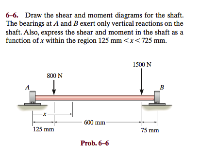
The bearings at A and B exert only vertical reactions on the shaft. Also express the shear and moment in the shaft as a function of x within the region 125 mm. In the last section we worked out how to evaluate the internal shear force and bending moment at a discrete location using imaginary cuts.
Draw the shear and moment diagrams for the shaft if it is subjected to the vertical loadings. The bearings at A and Bexert only vertical reactions an the shaft. Draw the shear and moment diagrams for the shaft.
Draw the shear and moment diagrams for the beam- The two segments are joined together at B. Start your trial now. KN 103 N.
Draw the shear and moment diagrams for the beam and determine the shear and moment throughout the beam 10 kip 2 kipft g Kip 8 kip 40 kipft as functions of x. There is a thrust bearing at A and a journal bearing at B. F 200 Ibquad w 100 frac Ib ft quad M 300 Ibftquad a 1 ftquad b 4 ftquad c 1 ft.
There is a thrust bearing at A and a journal bearing at B. Students also viewed these Sciences questions Draw the shear and moment diagrams for the shaft. Take P 6 kip.
The bearings at A and D exert only vertical reaction on the shaftThe loading is applied to the pulleys at B and C and E. Draw the shear and moment diagrams for the shaft. 300 mm 250-mm dia.
600 lb The FBD of the shaft is shown in Fig. First week only 499. Students also viewed these Sciences questions Draw the shear and moment diagrams for the shaft in terms of.
The maximum shear stress in the shaft is. But to draw a shear force and bending moment diagram we need to know how these values change across the structure. The support at A is a journal bearing and at B it is a thrust bearing.
Draw the shear and moment diagrams for the shaft The bearings at A and B exert only vertical reactions on the shaft. Sallow Mmax c I. The bearings at A and B exert only vertical reactions on the QQ shaft.
8 kip 3 kipft 5 ft 620. A The shear and moment diagrams are shown in Fig. Draw the shear and moment diagrams for the shaft.
Determine the critical point 3. Take d1-01 m d2 03 m d3 02 m d4 02 m F1-599 N F2-394 N and F3 199 N F2 F1 d2 d3 di d4 F3. Draw the shear and moment diagrams for the shaft.
Draw the shear and moment diagrams for the shaft in terms of the parameters shown. KN 103 N Given. F R LA dA w 0 L L 0 sina p L xbdx 2w 0 L p w 0 w w 0 sin x A B w x L 2 p L L 2 The moment of inertia of the cross-section about z and y axes are For the bending about z axis.
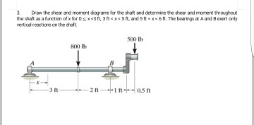
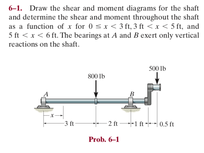
Draw the shear and moment diagrams for the shaft and determine the shear and moment throughout the shaft as a function of x for 0 x 3 ft 3 ft x 5 ft and 5 ft x 6 ft. Draw the shear and moment diagrams for the shaft in terms of the parameters shown. Draw the shear and moment diagrams for the shaft in terms of the parameters shown.
Shear and Moment Function. -N0 mm- 250 mim 24 kN. There is a thrust bearing at A and a journal bearing at B.
B A 800 lb 30 in. Draw the shear and moment diagrams for the shaft. The bearings at A and B exert only vertical reactions on the shaft.
A 2 m. As shown on FBD. Draw the shear and moment diagrams for thebeam.
Draw the shear and moment diagrams for the shaft. The allowable bending stress is sallow 22 ksi. The journal bearings at A and C exert only vertical reactions on the shaft.
The bearings at A and B exert only vertical reactions on the shaft. 1- Draw the shear and moment diagrams for the shaft and determine its required diameter to the nearest 18 in. 1500 N 800 N 600 mm 125 mm 75 mm Prob.
A M -75x2 1050x - 3200 Ans-200 - 150x - 4 x - 4 2 M 0. Draw the shear and moment diagrams for the shaft and determine the shear and moment throughout the shaft as a function of x for 0 x 3 ft 3 ft x 5 ft and 5 ft x 6 ft. For x250 mm Vx RA 24 75 kN and Mx -24x 315x-250 75x 7875 Solution Shear and Moment Diagram of Cantilever Problem 6-1 Bending Mechanics of Materials R C Hibbeler.
- M 450x - 4 0 V 1050 - 150x cF y 0-150x - 4 - V 450 0 M lb ft V lb 200 200 450 475 450 x x Ans. Determine the principal stress and maximum shear stress. The support at A is a thrust bearing and at B it is a journal bearing.
For x 250 mm The Shear Vx -24 kN and the moment Mx -24x. Solution for Draw the shear and moment diagrams for the beam loaded as shown. 270 N 1800 N.
Weve got the study and writing resources you need for your assignments. X N An A i nB J 6 ll MJotr --j F -ft 81563 800-. For the bending about y axis.
F1 400 lb.
Solved Draw The Shear And Moment Diagrams For The Shaft And Chegg Com
Solved 6 1 Draw The Shear And Moment Diagrams For The Shaft Chegg Com
Solved 6 6 Draw The Shear And Moment Diagrams For The Shaft Chegg Com
No comments for "Draw the Shear and Moment Diagrams for the Shaft"
Post a Comment